 ar
ar bg
bg hr
hr cs
cs da
da nl
nl fi
fi fr
fr de
de el
el hi
hi it
it ko
ko no
no pl
pl pt
pt ro
ro ru
ru es
es sv
sv tl
tl iw
iw id
id lv
lv lt
lt sr
sr sk
sk sl
sl uk
uk vi
vi et
et hu
hu th
th tr
tr fa
fa ms
ms hy
hy ka
ka ur
ur bn
bn mn
mn ta
ta kk
kk uz
uz ku
ku
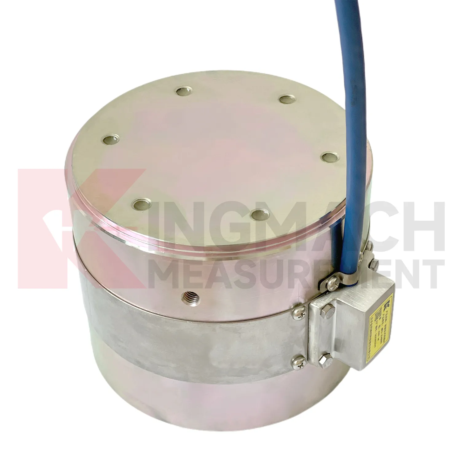
load cell calibration
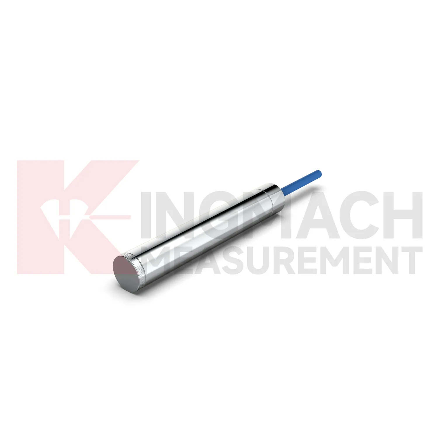
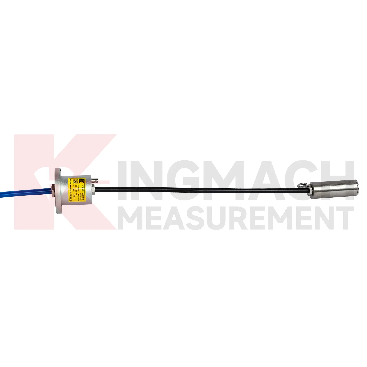
Kingmach load cell calibration for axial force monitoring addresses a common site problem: steel supports in deep foundation pits and tunnels can gain load quickly as excavation progresses. The JMZX-38XXHAT axial force load meter is listed in 200 kN, 500 kN, 1000 kN, 2000 kN, and 3000 kN ranges, with 0.1 kN or 1 kN sensitivity and 0.5%FS accuracy. Its product page lists a 1 MPa waterproof rating, automatic temperature correction, imported high strength steel wires, and direct axial force display in kN rather than only vibrating wire frequency. Claw type installation accessories are provided to help field placement. These features make the product relevant for temporary support monitoring, tunnels, tailings ponds, bridges, buildings, railways, transport, hydropower, and dams. Kingmach also notes that many axial force meters are customized, with model, range, and dimension confirmed at order. That matters when the support diameter, bearing plate thickness, and available clearance are already fixed by the construction design. The brand information also points to practical supply details, including Changsha origin, project use across transport and hydropower works, readout compatibility, and packaging for precision sensors. For engineering buyers, these details help connect catalog parameters with delivery, calibration, installation, and later service expectations.

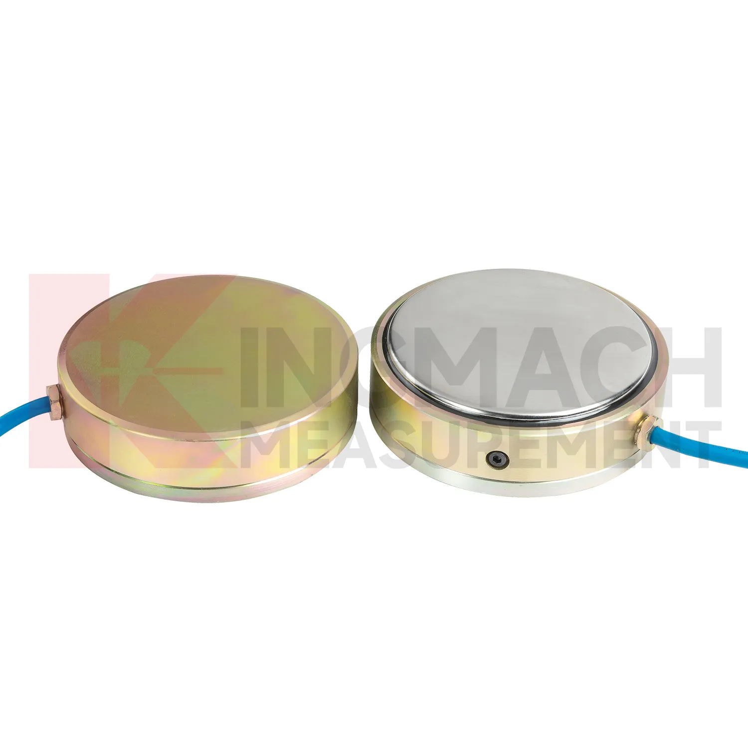
Application of load cell calibration
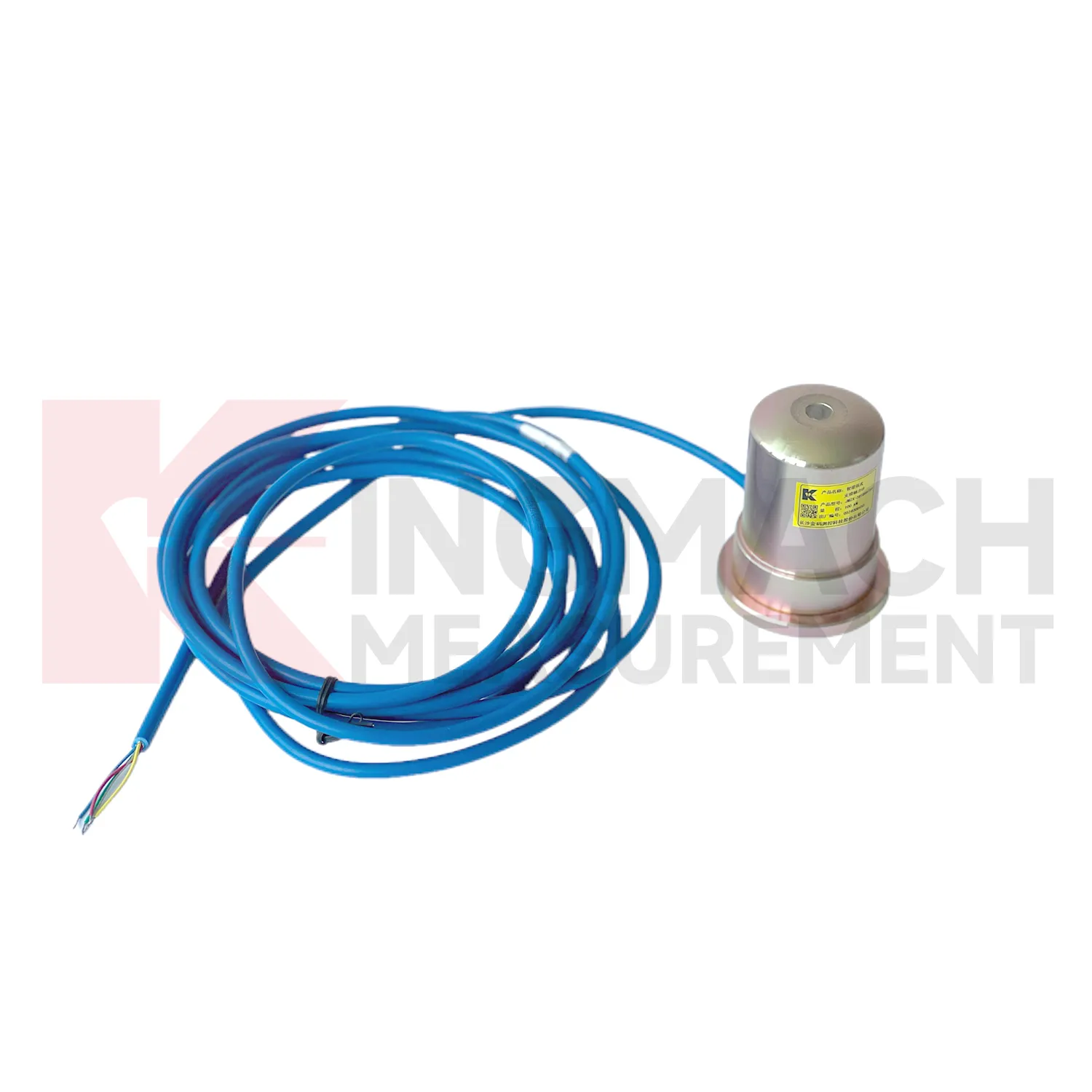
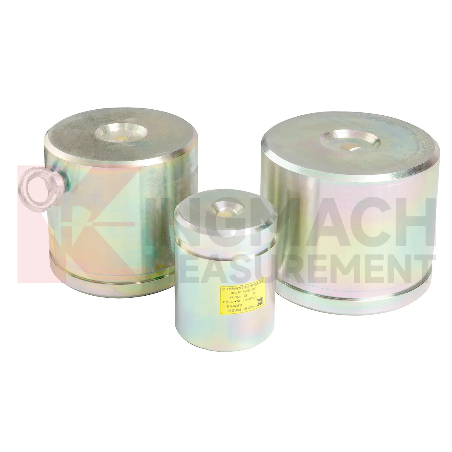
In pile load testing and bearing capacity verification, load cell calibration helps track applied force, load stages, unloading response, and residual behavior. The common problem is uncertainty around whether the applied load is centered and whether the recorded value matches the actual force passing through the test system. Kingmach solid load cells such as JMZX-35XXHAT list 1000 kN to 10000 kN ranges, 0.1 kN resolution, and 0.5%FS precision, with overload information listed as 20 to 50%F.S. range overload and 300 to 400%F.S. failure overload. These figures suit heavy test work when capacity margin must be checked before the sensor is installed. During the test, the record should include each loading step, hold time, unloading step, zero check, temperature, and any change to the bearing arrangement. Pairing the load record with settlement readings gives a clearer view of pile response. After the test, the documented calibration coefficient and instrument identity help keep the acceptance file defensible. Test reports should also record jack pressure, settlement response, load rate, hold duration, and any adjustment to the reaction system. These records help engineers identify whether an unusual load value came from the pile, the loading setup, or the measurement chain.
The future of load cell calibration
The next stage for load cell calibration in infrastructure monitoring is tighter integration with site data systems. Smart sensors already store model data, calibration coefficients, zero values, temperature readings, and measurement records on selected Kingmach products. The practical path is to connect that identity data with 4G, LoRa, wired acquisition, or 5G gateways, then place the force trend beside displacement, settlement, pore pressure, and rainfall in the same review screen. This matters because future warnings will be less about one limit value and more about patterns: force rising after excavation, anchor load falling after heavy rain, or bridge cable force drifting during seasonal temperature cycles. Digital twin models can use those readings when the sensor location, range, and calibration background are reliable. Standards and owner specifications for structural health monitoring are also becoming more data traceability focused, which favors instruments that can carry their own calibration identity and remain readable through long service periods.
Care & Maintenance of load cell calibration
For load cell calibration connected to automated acquisition, maintenance is partly physical and partly digital. At installation, confirm sensor model, range, channel number, unit, calibration coefficient, zero value, and temperature channel before the point is accepted. Smart load cells may store calibration information and up to 800 measurement records, while digital output and anti-interference transmission help long cable runs. During operation, review missing data, repeated identical values, sudden jumps, and temperature related drift. Physical checks should cover waterproof connectors, cable strain relief, grounding, lightning protection, junction boxes, and power supply stability. After any software or logger change, verify that kN or MPa units remain correct and that historical trends did not shift because of scaling errors. Where alarms are used, test the alarm path without applying dangerous loads. A good maintenance routine protects the instrument and the database at the same time, because either one can damage confidence in the monitoring record.
Kingmach load cell calibration
load cell calibration often sits between design intent and field behavior. Drawings may state the expected force, but site loading can change when excavation sequence, concrete curing, traffic, reservoir level, grouting, or prestressing work changes. Kingmach supplies sensors and acquisition equipment for bridges, tunnels, dams, subways, slopes, foundations, railways, buildings, and hydropower projects. In these settings, the sensor helps reveal whether a member is carrying its share of the load or taking more than expected. The instrument must fit the force range, the bearing surface, the environmental exposure, and the data workflow. A high capacity sensor with poor installation records is still hard to trust. A moderate range sensor with clear calibration, stable zero, protected cable, and a clean reading plan can produce stronger evidence. For that reason, force monitoring should be planned alongside installation details, not added after the site has already become crowded. This is especially useful when the monitored point becomes hidden after the next work stage.
FAQ
Q: How should load cell calibration be selected for a bridge cable or anchor point? A: Start with expected force, lock-off load, possible overload, bearing geometry, and access for later inspection. Hollow load cells are commonly used where the anchor or cable passes through the center opening. Q: What range information is available from Kingmach hollow models? A: The JMZX-3XXXHAT series is listed from 500 kN to 8000 kN, with 0.1 kN sensitivity on the 500 kN model and 1 kN on larger listed models. Q: Why does temperature correction matter? A: Cable and anchor readings can move with temperature, so built-in temperature measurement helps reduce false interpretation. Q: Can readings be stored inside the sensor? A: Smart hollow models list storage for 800 measurement records, including time, temperature, zero values, and correction data. Q: What should be checked after installation? A: Check seating, cable protection, connector sealing, zero value, first stable force, and matching channel name.
Reviews
Andrew Lee
The visualization software is intuitive and powerful. It helps us analyze monitoring data efficiently.
Robert Taylor
The weir flow meter is well-built and delivers accurate measurements. Great value for water management applications.
Latest Inquiries
To protect the privacy of our buyers, only public service email domains like Gmail, Yahoo, and MSN will be displayed. Additionally, only a limited portion of the inquiry content will be shown.
Evelyn***@gmail.comSouth Africa
Hi, we are a contractor working on tunnel construction and need settlement sensors and displacement ...
Sophia***@gmail.comUnited Kingdom
Good day, we need environmental monitoring sensors including temperature, humidity, and wind sensors...
Related product categories
- calibration of load cell theory
- load cell failure
- load cell technology
- strain gauge load cell wiring
- diagram 4 wire load cell wire connection
- load cell accuracy calculation
- load cell amplifier circuit
- load cell calibration procedure
- load cell excitation voltage
- load cell unit of measurement
- mounting load cells
- strain gauge with load cell